もっと知りたい場合は?
 The LaserSpeed has one laser diode source but it is split into two beams
that exit the gauge aperture at an angle.
The LaserSpeed has one laser diode source but it is split into two beams
that exit the gauge aperture at an angle.
The two beams converge and overlap at the
standoff distance.The distance from the front of the gauge to the center of the depth of field
The overlap region is called the
depth of field.The vertical measurement region of the gauge. Measurements can be taken within this region
The fringe patterns are generated by the two laser beams exiting the LaserSpeed.
If you take two coherent light sources that are the same wavelength
and cross their paths at an angle, a fringe pattern is generated.
As the waves of light cross each other, the peaks line up to create
a light stripe. As they continue to cross, the peaks and troughs line up to cancel each other out. This
pattern repeats throughout the
depth of field.The vertical measurement region of the gauge. Measurements can be taken within this region
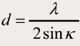


 The formulas to the right show the mathematics behind the measurement principle.
'd' is the fringe spacing. 'f' is the frequency, which is determined by
the
scattering As a particle on the surface moves through
the light and dark stripes of the fringe pattern, a time varying signal is generated and
read by the LaserSpeed
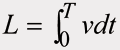
of light from the measurement surface. Since 't' (time) is the inverse of frequency,
we have the two parameters to calculate velocity, 'v'.
The formulas to the right show the mathematics behind the measurement principle.
'd' is the fringe spacing. 'f' is the frequency, which is determined by
the
scattering As a particle on the surface moves through
the light and dark stripes of the fringe pattern, a time varying signal is generated and
read by the LaserSpeed
of light from the measurement surface. Since 't' (time) is the inverse of frequency,
we have the two parameters to calculate velocity, 'v'.
速度を時間積分し長さが求められます。
計算式を記憶する必要はありませんが、フリンジ(間隔)距離'd'は波長、ビーム角度により決まります。 更に、これらの2つのパラメータを制御し、一定に保つ事ができます。 これにより、フリンジ間隔'd' は不変に保たれます。
間隔'd'が変化しない限り、レーザースピードプロを校正する必要はありません。
レーザスピードが測定長さ、速度をどのように使用可能インターフェースに変換するのか?
主要インターフェースはパルス出力です。 レーザースピードプロは単位長さ当りのパルス数を任意に設定できます(分解能)。一度設定すれば、速度に応じたパルスを出力します。
速度、方向が一方向であれば、パルスは1チャンネルで充分です。
方向性が必要になると、2チャンネル必要となります。
This is called
quadrature
Quadrature x1 mode -
The counter adds 1 count after A then B goes high
Quadrature x2 mode -
The counter adds 1 for each falling edge of A and B
Quadrature x4 mode -
The counting devices adds 1 for each rising and falling edge of A and B
counting. Two channels, A and B, generate pulses 90 degrees out of phase.
If A leads B, then the direction is positive. If B leads A, then the direction is negative.
Both True and False signals are generated for added noise immunity.
